Kapta calibration
The calibration of a Kapta is an essential step to ensure the accuracy of the tracking system. After having installed the Kapta over the desired tracking area, you need to calibrate it. This calibration is done via the Kratos software.

Calibrating a Kapta is finding the position and rotation of each of its cameras relative to Kratos coordinate system. For now, the calibration is done by forming a rectangle of known dimension and position on a horizontal plane in the tracking zone and then by matching this rectangle to a virtual rectangle in the viewpoint of each camera.
Kapta installation
Before performing the calibration of a Kapta, make sure that it is correctly and securely installed, and that the point of view of each camera covers the entirety of the desired tracking area and is not obstructed by any object.
The 2 thermal cameras have a FoV slightly smaller than the other cameras.
So make sure that the left thermal camera sees the right side of you tracking area and vice versa.
If the Kapta is moved after the calibration, the calibration will have to be redone to obtain optimal results.
If the truss on which the kapta is rigged is lowered for any reason, it will not be raised to the exact same height, resulting in an error in the Z measurement of the tracked individuals' positions. Depending on the situation, this error may be considered acceptable or not.
When the Kapta is installed and connected to Kratos, you can start to draw the calibration rectangle
Calibration rectangle creation
You first need to draw a rectangle on the floor of your tracking area. This rectangle must follow the following rules :
- Must be of known dimensions and position.
- Must be placed on a horizontal plane (it can be at a known height from Z = 0, but it must be horizontal).
- Must have its sides parallel to the X and Y axes of the Kratos coordinate system.
- Must be composed of 6 points : 1 point for each corner and 1 point at the middle of the sides that are parallel to the X axis.
- Be visible by all the cameras of the Kapta.
For the calibration to be the most precise possible, the rectangle must be as large as possible without being in the distortions of one of the Kapta's cameras.
- If you draw a 1 x 2 meter rectangle on a 10 x 10 meter tracking area, the calibration will be less precise than if you draw a 5 x 10 meter rectangle on the same tracking area.
- Try to avoid being in the distortions of the camera, the sweet spot is when the rectangle occupy 2/3 of the camera's FoV.
- If you are on a stage constructed with plates of knows dimensions, you can use the lines between the plates to draw your calibration rectangle quickly.
- Try to calibrate the Kapta at a moment when the tracking area is empty, so that the rectangle is not obstructed by any object (riser, speakers, etc.).
- If you are in a tour situation, you can draw your rectangle on a large piece of fabric that you can then roll up and carry with you, making the calibration process easier.
The size of the calibration rectangle doesn't define the tracking area.
By definition, the possible tracking area is all the space that is visible by all the cameras of the Kapta. The calibration rectangle is only used to calibrate the Kapta.
When the rectangle is drawn, you can start the calibration process.
Calibration window
To calibrate a Kapta on Kratos, go to a Show explorer view, select the desired Kapta and click on the "CALIBRATE" button. A calibration window will appear :
This windows is divided in 3 pages :
- Stage dimensions page, where you provide the dimensions and position of the rectangle you drew on the floor.
- Calibration targets page, where you match the virtual rectangle on each of the camera viewpoints to the rectangle you draw on the floor.
- Check page, where you check the final calibration result.
You can navigate from one page to another with the "BACK" and "NEXT" buttons. After opening the calibration window for the first time, the next time you open it, it will open on the last page you were on.
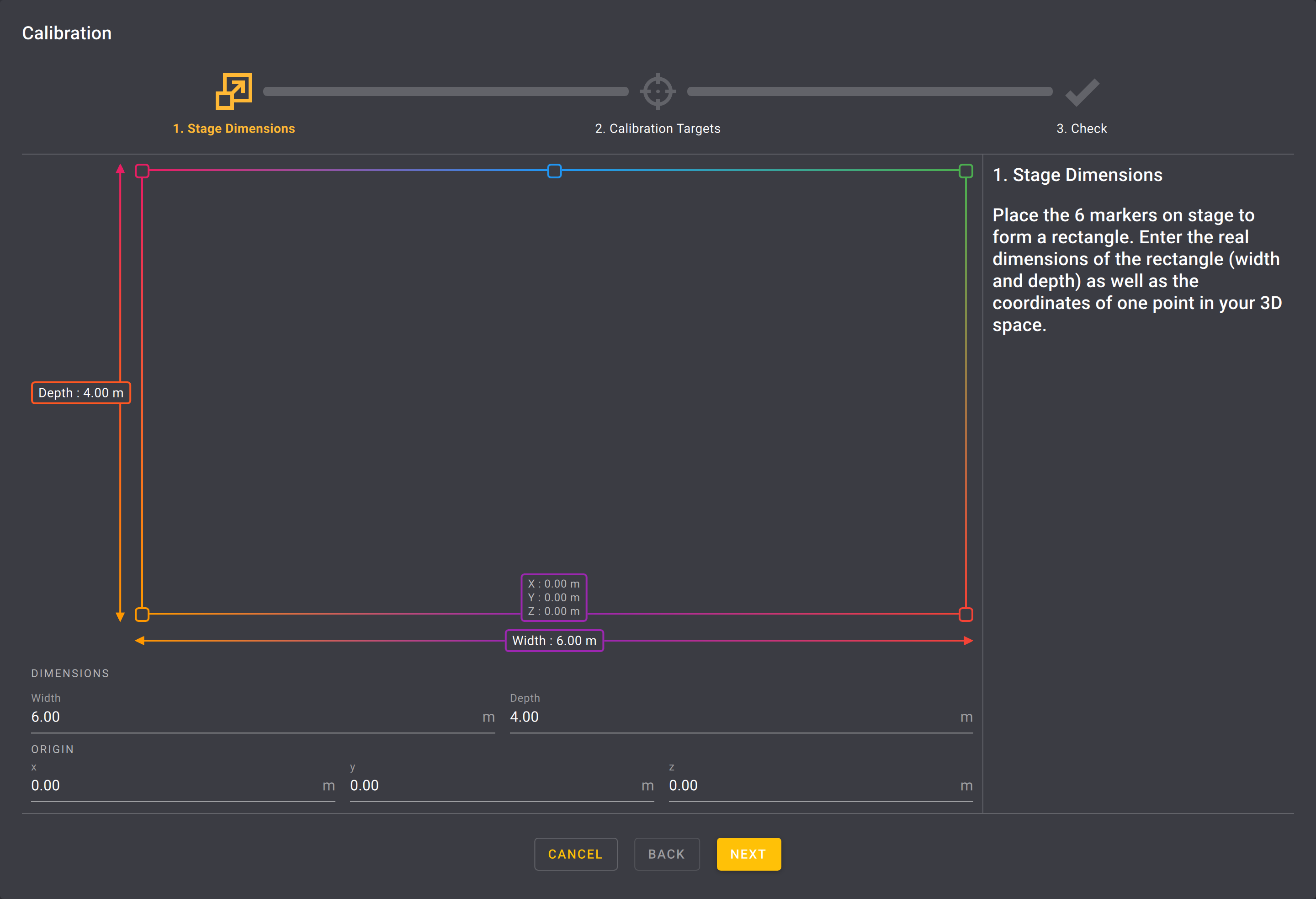
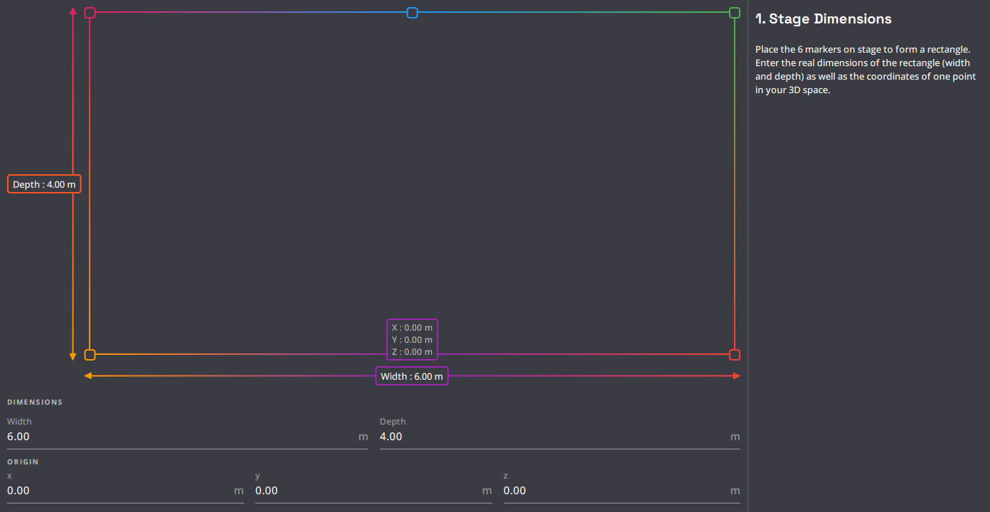
Stage dimensions
In this page, you have to enter the dimension and position of the calibration rectangle you drew on the floor.
- The
Widthfield is always the dimension (in meters) of the sides that are parallel to the X axis of Kratos coordinate system. - The
Depthfield is always the dimension (in meters) of the sides that are parallel to the Y axis of Kratos coordinate system. - The
ORIGINfields are the position (in meters) of the purple point, which is always the middle point of the X-parallel side that has the smallest Y position of the two middle point.
Please follow the previous guidelines on point definition carefully.
This is what allows the Kapta to calibrate its position correctly in the Kratos coordinate system.
You can hover on a calibration point to see its coordinates.
When the dimensions and position of the rectangle are entered, you can go to the next page.
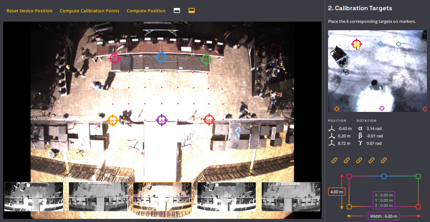
Calibration targets
On this page, you have access to the point of view of each of the Kapta's cameras. For each one of them, you will have to drag 6 targets on their corresponding point of the calibration rectangle.
- You can zoom on each image to place the targets more precisely.
- The relative position of each camera is calibrated from the factory, but this calibration is not precise enough to calibrate all cameras with only one camera, and can change over time (if the Kapta experiences shocks for example). But this calibration can be used to help you re-position the targets on each camera viewpoint quickly. After having pre-placed the targets, you need to delink the cameras with the corresponding buttons and place the targets more precisely on each camera.
- The pink points on the cameras views represent a grid of 1mx1m.
- For the visible light and NIR cameras, depending on what you used to mark the calibration points, you can see the points on the images. If this is not the case, you can ask for someone to put their finger tip or fist (depending of the distance of the point from the Kapta) on the point to make it visible.
- For the thermal cameras, we recommend that someone put their finger tip (or fist) on the point to make it visible. This can also work with a hot object (like a hot cup of coffee) or a cold object (like a glass of water taken out of the fridge).
- If you are alone, you can record yourself marking the point with your finger tip on a
.kramerafile, play the file in the simulator, calibrate the simulated Kapta and then use the calibration on the real Kapta.
Be careful about the colors of the targets when placing them.
The purple target is always the middle point of the X-parallel side that has the smallest Y position of the two middle point. You can use the colors of drawing at the bottom right of the window to make sure that the targets are correctly positioned from one to another. If your Kapta is not positioned along the X axis of the Kratos coordinate system, looking toward the positive Y axis, you need to rotate the calibration rectangle accordingly by moving all the targets.
| Image | Explanation |
|---|---|
 |
If the targets are outside the camera point of view or if they are disorganized, you can use this button to reset the position of the Kapta to a standard position and thus have the targets make a rectangle. |
 |
This button allows you to replace the position of the calibration targets in function of the current position of the Kapta and the dimensions and position of the calibration rectangle provided in the previous page. |
 |
If you change the dimensions or the position of the calibration rectangle in the previous page, you need to click on this button for the changes to take place and to reevaluate the position of the Kapta. |
 |
Theses buttons allow you to delink each cameras to the Kapta rig. If a camera is delinked, moving a target on it point of view will not move the corresponding target on the cameras still linked to the Kapta rig and vice versa. |
The tracking performances of the K SYSTEM depend on the quality of the calibration. So take your time to make sure that the targets are well placed on the points for each camera.
When the 6 targets are placed on each camera viewpoint, you can go to the next page.
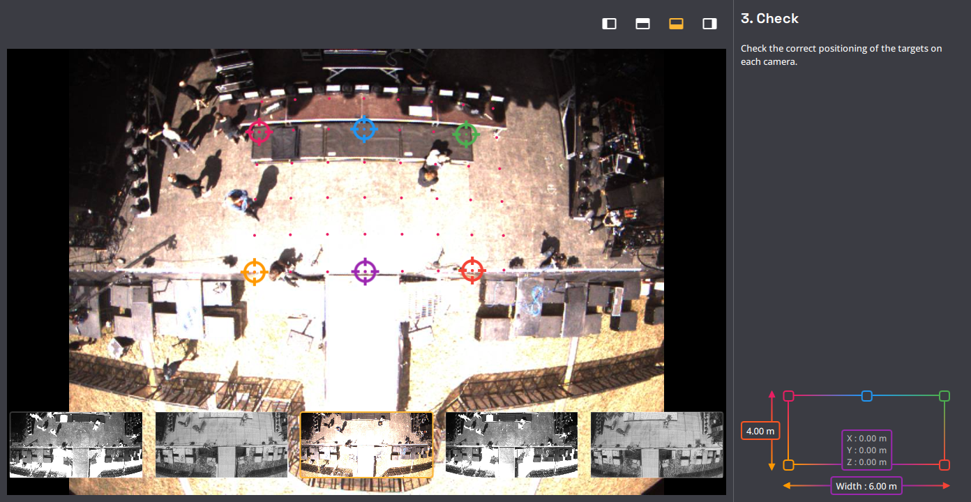
Check
This next page allows you to check the calibration result.
We recommend to save the calibration by exporting it every time you perform one.
When the calibration is done and the calibration window is closed, click on the "EXPORT CALIBRATION" button in the Show explorer view. This will allow you to re-import the calibration if you need to re-calibrate the Kapta.
Multi Kapta setup
If your setup uses 2 Kaptas to extend the possible tracking area, you have to calibrate them separately.
You can use a different calibration rectangles for each Kapta as long as their dimensions and position are referenced in the same coordinate system.
If the two Kaptas have a bit of overlap in their point of view, they will form a continuous tracking area.
Allowing for the identity of each Target to be kept when they go from one Kapta to the other.